This feed contains pages in the "make" category.
I needed a coat stand. I had a pile of coats on the floor and some hung up on g-clamps on the back of a door. It was not the best of solutions. So after some searching on the web I decided that there where none that I really liked. So I thought I would make one for myself. Just three months later and I have something that I am happy with.
My final design came to me in the concrete isle at B&Q. So I brought some cement, sand, and a bucket. Next up was 2m of steel box section, Some coat hooks and a set of LED garden lights. (What? Every coat stand needs lights) My idea was simple. Use the bucket as a mould for a concrete base and the steel box as the upright and attach the hooks at the top. The bonus was setting the lights into the concrete for extra class.
I like to let these things form in the back of my mind so I got it all home and put it by the pile of coats for a bit. First off was spacing the lights. As I sat eating a ready meal I noticed that it came in a metal tin just a little smaller than bottom of the bucket I was going to be using to make the base. Sorted.

I printed out a template with 10 evenly spaced holes round a circle. Stuck it to the tin and drilled some holes. It turns out drilling 10mm holes in tinfoil does not really work and a punch would have been better I think but I got there in the end. Now I fed in all the lights and created this squid like creature.


I decided to stick the lights to the bottom of the bucket using blue tack which mostly worked but I think I would try double sided tape next time I think. The blue tack left the lights quite recessed in the concrete. The idea with the concrete was to form a large lump at the base. By filling the bucket as a mould then turning that out and over I should have a nice smooth dome. Sticking the lights to the bottom of the bucket should make them shine up from the top of the base in the final part so that is what I did. For the box section I just wrapped it in a plastic bag and dropped it into the centre of the bucket so that when the concrete had set I could pull it out again. This did allow me to get it straight and worked pretty well.


I mixed up some rather runny concrete about one to one cement and sand and dribbled it into the bucket. Not really having a clue what I was doing I just hoped that would be okay. I had intended to make three layers with different shades but in the end went with just two.

I filled up the bucket to just above the level of the tin, trying not to knock the lights off their bases. Ithen let that dry for a few days. Adding a second layer to bring it most of the way up the bucket. I think that I should have made more of an effort to clean up between the layers as it did leave some marks on the edges a little. Just cleaning the edget of the bucket and sweeping it to the middle would have done I think but it looks okay.

The big reveal came a week or so later as I wanted to be sure that it had a good chance to set. The pole pull out without to many problems. and the bag followed quite simply so I was happy with that. I turned the bucket upside down over a couple of sticks so that it did not fall on the wires and started to tap. With not much effort at all it dropped out. I was fully expecting to have to destroy the bucket to get it off but it seemed to work really well. The top is really smooth and I was really impressed with how it came out. I quite like the fact you can even see the litre markings from the bucket up the side. The join is a little rough and I may end up making a band to cover it up but for now I will just say it adds character.


All but one of the lights had stuck down okay and with just a little work with a screwdriver the blue tack and the edge of the concrete could be cleaned away simply enough. I think the tin foil tray had mostly kept the last one in place so it was not to bad and is just a little more recessed.
Putting the pole back into the top and three little wooden feet underneath plus one more for the bottom of the pole. I switched on the lights and had a rather elobrate storage for one hat. I left the lights on for a bit and they did not seem to get even slightly warm so I hope they will be okay. They are rather bright so I might look at running them from 6 or 9 volts rather than the 12 they currently run at.

Now for the hooks. I brought four simple aluminuum hooks with 3 prongs on each and my first thought was just to drill holes in the steel pole and attach them straight on but somebody pointed out that may leave the hooks a little close to each other. I decided to get a couple of bits of wood and clamp them round the pole and then screw the hooks onto that. It was about that time that my 3D printer sprung back into life so after a little messing about in OpenCAD I designed a block that I could slip over the top of the pole and attach the hooks to. Sorted.

I then used some match sticks to wedge the top and bottom of the pole in place and then some Sugru to tidy up the hole a little and I was done.


 I am pretty happy with it. It's unique and quite neat I think. There are some things that I think I would change. Using sticky tape for holding down the lights would make them more flush. Taking out the pole at the second or third layer and sealing the hole with a plate so that the pole does not sit directly on the floor needing a wooden plate to spread the weight. I think that the join on the concrete could have been cleaner if I had made more of an effort to tidy it up before starting the next layer. I might get a second bucket to mix the concrete in as doing it in an old innocent lunch pot was a little slow going!
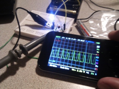
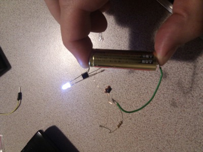
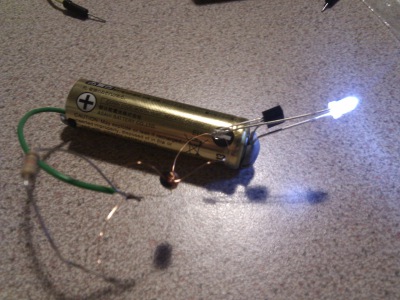
Made my joule thief at York Hack Space last night. Most tricky part was winding the coils around the ferrite bead. I was supposed to get 20 turns onto it but I think the beads I brought where a little on the small side. I managed to get 13 or 14 turns on in the end and it works a treat. The final version is running on my desk right now and I have upgraded the bluetak to an elastic band. I will put printing a case for it on my reprap list.
It looks to be only oscillating at 2khz rather than the 50khz I was told to expect but is working great for a battery that was showing less the 1v.
Reading how the circuit works it looks like you could drive any voltage from the coil with a diminishing return in current. I wonder if there would be an optimal number given the components I have.
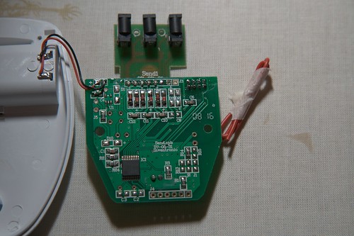
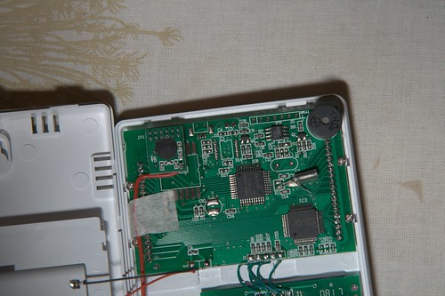
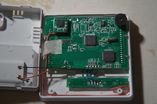
I brought at efergy energy meter from Oxfam and have had it running for a couple of days and it is already starting to annoy Sarah. Next up is to try and grab some of that data and graph it.
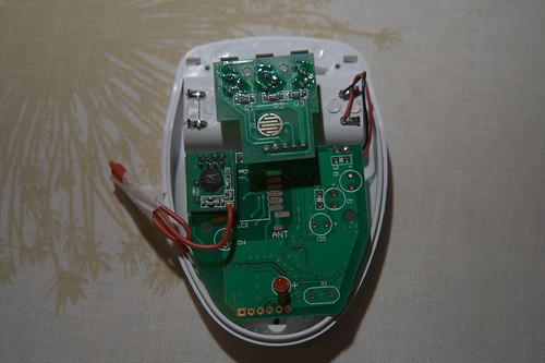
I sent an email to efergy asking if they could let me have some more information about the specs of the signal. I got a really good reply from them saying that they could not really give me any more detail than is on the box which is what I expected but the guy there did seem interested in what I was doing and took the time to write out quite a detailed reply so I like the company already.
The spec says that every six seconds the transmitter spits out a signal on the 433Mhz band so my next step is to try to capture that. If I had more than a multimeter then this may be a lot simpler but hey lets give this a go. I am going to get a 433Mhz reciver for a garage remote so that I can get the baseband signal. Assuming they are sending very little data then the bandwidth should be pretty low so I think that if I can get the arduino to capture the output at say 20kb/s then I should be able to examine the signal if it is less than 10Kb/s. It may be simpler to just try and grab this direct from a parallel port.
Built me a remote for my new camera.

On the side of my camera is a 2.5mm stereo jack socket that can be used to remote control the shutter release. During the last few dark shots I have been using the timer to try and avoid camera shake but this means that you have to wait an extra ten seconds before the shot fires.
After a bit of research I found a couple of sites that showed how simple it was to create a switch box to control it all. After digging around my box of bits for a while I decided that I would leave the speak and spell controlled remote for another day and head down to Maplins.
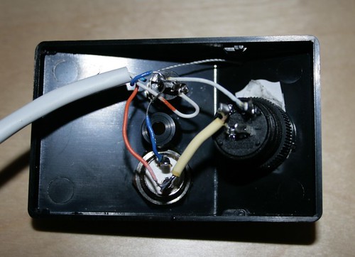
After a slight error of buying the wrong type of switch ( Hey it was in a row of push-to-make switches and had no label saying any different how was I supposed to know it was a push-to-break version!) I now have constructed what looks like a nicely homemade version a remote control complete with a latching switch for long bulb exposures. Time to get out tonight and grab some photos.